Xtool X100 Pad3 is a professional tablet key programmer. It’s available with key programming and 16 advanced special functions. Equipped with KC100, X100 PAD Elite can work with VW/Audi/Skoda/Seat 4th & 5th immobilizer software and BMW CAS1-3 & CAS4 immobilizer software. Compatible with XTOOL KS-1, it can support Toyota/Lexus all keys lost without disassembly.

Part 1: XTOOL X100 PAD Elite program IMMO for VW 4th/5th
Let’s take VW as an example firstly.
Since VW 4th and 5th IMMO programming needs online programming, please make sure X100PAD3 connect Internet before doing programming.
Guide & tips to program VW 4th/5th IMMO online:
Step 1: Connect X100 PAD Elite to the OBD port of vehicle via main cable and OBDII connector (or other relative connector)
Step 2: Connect X100 PAD3 and KC100 via USB and mini USB cable

Step 3: Turn on the ignition switch, then run X100PAD3 application
Select Immobilization- >VW -> 4th /5th Immobilizer system
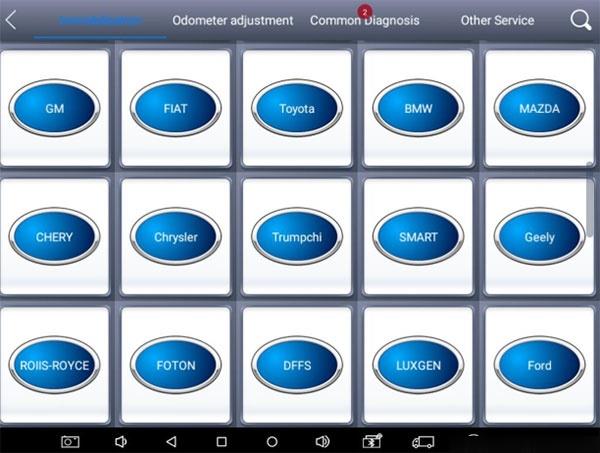
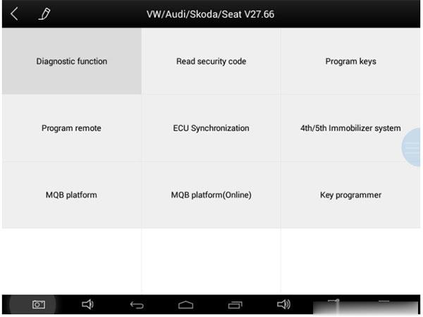
Step 4: Select the corresponding Immobilizer system
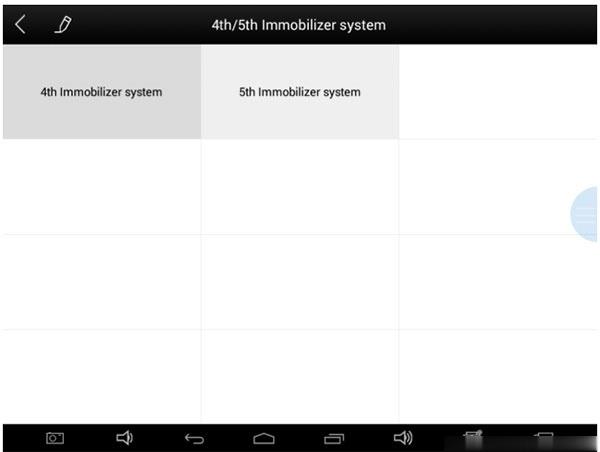
Tips: If your car is 4th immobilizer system, please select 4th immobilizer system.
If your car is 5th immobilizer system, please select 5th immobilizer system.
It will detect your meter type automatically, if it does not detect successfully, you can choose your meter type manually.
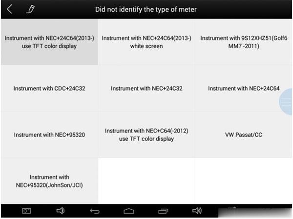
Step 5: Then follow the instructions that software reminds you to add new keys.
Part 2: XTOOL X100 PAD Elite add new key to Toyota/Lexus all keys lost
Connect the devices as same as above firstly, turn on ignition, run software application
Select Immobilization- >Toyota ->All smart key lost-> Read immobilizer data
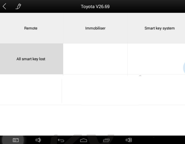
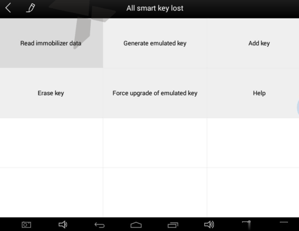
Follow the prompt to press car’s START button to read the data.
When read out data, save it with a new file name
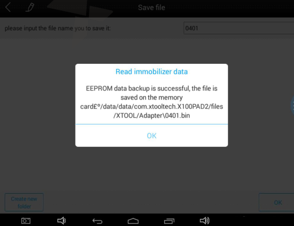
When generatingKS-1Toyotasimulatorkey, please connect KC100 firstly
Note: the device must be connected to the network
Press Generate emulated key-> select the backup immobilizer file-> confirm the current key type shown on the screen
The system will upload data to Xtool server for data verification and calculation.
After verification, it will activate KC100
Put the KS-1 simulator card intotheKC100’ slot and follow the instructions to complete the next operation.
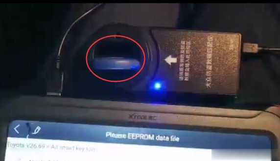
Bind X100 PAD3 with KS-1 Toyota simulator card
Generate simulator key
After the key is generated successfully, select Add key and follow the prompts to finish making key
fyi
1.Diagnostic Link Connectors Locations of Various Vehicle Models:
AUDI A6: the OBD plug is on the lower left side of the dashboard, use SMART OBDII-16 connector.
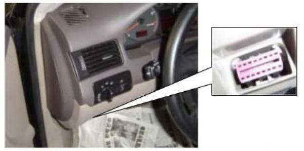
VW Bollywood 1.8: the OBD plug is below the console, use SMART OBDII-16 connector.
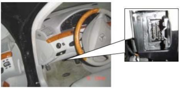
Benz S320, 220 Chassis: the OBD plug is below the dashboard, use SMART OBDII-16 connector.
Benz C180: the OBD plug is on the left hand side of the engine bay, use Benz-38 connector.
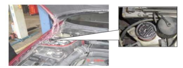
Benz 300SEL 140 chassis: the OBD plug is on the left hand side of the engine bay,
use Benz-38 connector.
GM Buick: the OBD plug is below the dashboard, use SMART OBDII-16 connector.
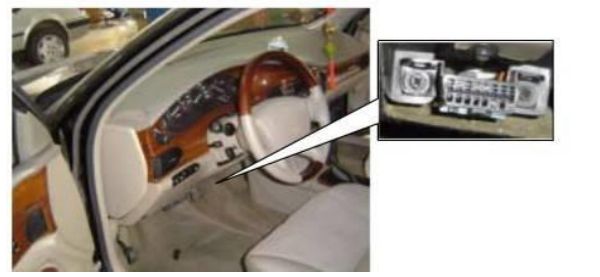
GM Buick: the OBD plug is below the dashboard, use SMART OBDII-16 connector.
GM Buick GL8: the OBD plug is below the dashboard, use SMART OBDII-16 connector.
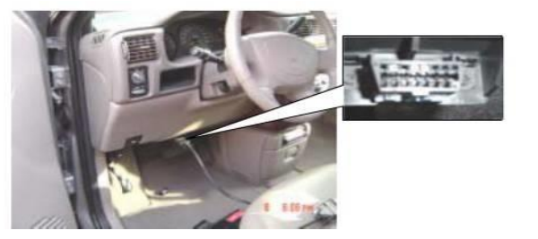
VW POLO: the OBD plug is below the dashboard, use SMART OBDII-16 connector.
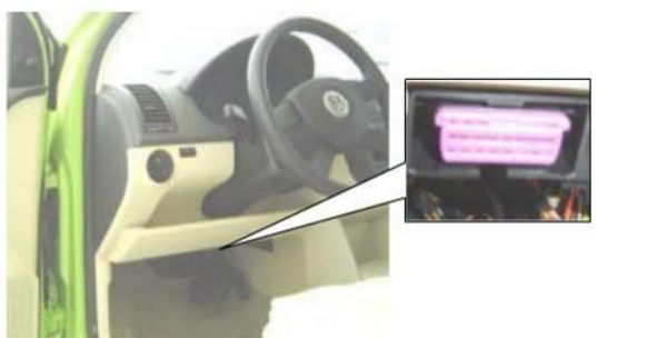
BMW 735I: the OBD plug is in the right hands side of the engine bay, use BMW-20 connector.
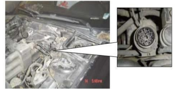
VW Passat B5: the OBD plug is behind the gearlever and beside the parking brake lever. Lift the cover to access it. Use SMART OBDII-16 connector.
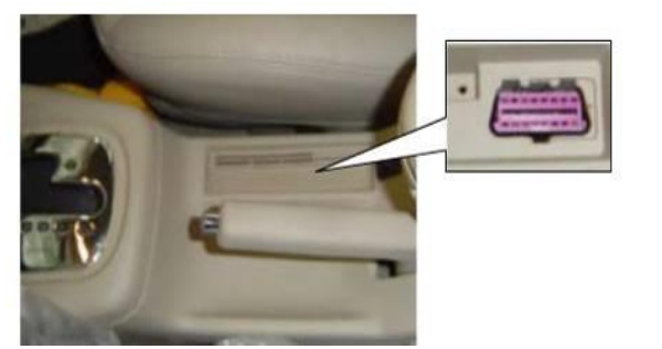
2.Location Diagram of Vehicle Diagnostic Link Connectors:
Location diagram of pick-up truck diagnostic link connectors:

Location diagram of utility vehicles diagnostic link connectors:

Link diagram of small car diagnostic link connectors:

NOTE: Each vehicle manufacturer may use additional pins to diagnose a variety of systems. Not every manufacturer uses the same standard. The function on a certain pin will vary from manufacturer to manufacturer. Verify with the manufacturer.
3.Diagnostic Link Connectors Terminal Definition and Communication Protocols:
Standard OBDII Diagnostic Link Connector:
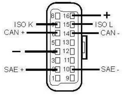

Pin Definition (Reference material)
Various pin definitions as follows:
Manufacturer definition
SAE J1850 bus positive
Manufacturer definition
Bodywork site
Signal site
ISO 15765-4 defined CAN high
ISO9141 and ISO14230 defined K line
Manufacturer definition
Manufacturer definition
SAE J1850 bus negative
Manufacturer definition
Manufacturer definition
ISO 15765-4 defined CAN low
ISO9141 and ISO14230 defined L line
Permanent positive voltage
[1] 1, 3, 8, 9, 11, 12 and 13 are defined by manufacturer.
[2] 2, 6, 7, 10, 14 and 15 are used for diagnostic communication. Unused definitions can be defined by manufacturers.