By establishing a data link to the electronic control systems of the vehicle being serviced through the Autel MaxiSYS Elite, the Diagnostics application allows you to retrieve diagnostic information, view live data parameters, and perform active tests. The Diagnostics application can access the electronic control module (ECM) for various vehicle control systems, such as engine, transmission, antilock brake system (ABS), airbag system (SRS) and more.
1.Establishing Vehicle Communication
The Diagnostics operations require connecting the MaxiSys Elite Diagnostic Platform to the test vehicle through the VCI device using the main cable, and test adapters (for non-〇BD II vehicles). To establish proper vehicle communication to the MaxiSys display tablet, you need to perform the following steps:
1.Connect the VCI device to the vehicle’s DLC for both communication and power source.
2.Connect the VCI device to the MaxiSys display tablet via BT pairing, USB connection, or Ethernet connection.
NOTE: To prevent short circuit damage to the device, it is recommended to connect the USB or the Ethernet cable between the VCI and the tablet before connecting the vehicle’s DLC.
3.When these are done, check the Autel OBD2 navigation button at the bottom bar on the screen, if the button displays a green tick icon at the lower right corner, the MaxiSys Elite diagnostic platform is ready to start vehicle diagnosis.
Vehicle Connection
The method used to connect the VCI device to a vehicle’s DLC depends on the vehicle’s configuration as follows:
1.A vehicle equipped with an on-board Diagnostics Two (OBD II) management system supplies both communication and 12-volt power through a standardized J-1962 DLC.
2.A vehicle not equipped with an OBD II management system supplies communication through a DLC connection, and in some cases supplies 12-volt power through the cigarette lighter receptacle or a connection to the vehicle battery
OBD II Vehicle Connection
This type of connection only requires the main cable without any additional adapter.
To connect to an OBD II vehicle
1.Connect the main cable’s female adapter to the Vehicle Data Connector on the VCI device, and tighten the captive screws.
2.Connect the cable’s 16-pin male adapter to the vehicle’s DLC, which is generally located under the vehicle dash.
NOTE: The vehicle’s DLC is not always located under the dash; refer to the user manual of the test vehicle for additional connection information.
Non-OBD II Vehicle Connection
This type of connection requires both the main cable and a required OBD 丨 adapter for the specific vehicle being serviced.
There are three possible conditions for Non-OBD II vehicle connection:
1.DLC connection supplies both communication and power.
2.DLC connection supplies communication and power is to be supplied via the cigarette lighter connection.
3.DLC connection supplies communication and power is to be supplied via connection to the vehicle battery.
To connect to a Non-OBD II Vehicle
1.Connect the main cable’s female adapter to the Vehicle Data Connector on the VCI device, and tighten the captive screws.
2.Locate the required OBD I adapter and connect its 16-pin jack to the main cable’s male adapter.
3.Connect the attached OBD I adapter to the vehicle’s DLC
NOTE:
Some adapters may have more than one adapter or may have test leads instead of an adapter. Whatever the case, make the proper connection to the vehicle’s DLC as required
To connect the cigarette lighter
a)Plug the DC power connector of the cigarette lighter into the DC power supply input port on the device.
b)Connect the male connector of the cigarette lighter into the vehicle’s cigarette lighter receptacle.
11.To connect the clipper cable
1.Connect the tubular plug of the clipper cable to the male connector of the cigarette lighter.
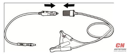
2.Plug the DC power connector of the cigarette lighter into the DC power supply input port of the J2534 programming device.
3.Connect the clipper cable to the vehicle’s battery.
VCI Connection
After the VCI device is properly connected to the vehicle, the Power LED on the VCI device illuminates solid green light, and is ready to establish communication with the MaxiSys display tablet.
The J2534 ECU Programming Device, which comes with the MaxiSys Elite tool kit, supports 3 communication methods with the MaxiSys display tablet: BT, USB,and Ethernet connection.
Pairing Up via BT
Among all methods,BT pairing is recommended as the first choice for the communication between the MaxiSys display tablet and the VCI device. The working range for BT communication is about 755 feet (230 m); this means you can perform vehicle diagnosis freely around the workshop with greater convenience.
If you use more than one VCI device to connect to the test vehicles when customers are many, you can perform vehicle diagnosis on various vehicles conveniently, by pairing the MaxiSys display tablet separately to each of the VCI devices connected to the different test vehicles, via BT, without the need to repeat the plugging and unplugging procedure, which is unavoidable through traditional wired connection, thus saves you more time and provides more efficiency.
To pair up the MaxiSys display tablet with the VCI device via BT
1.If not already done, power up the MaxiSys display tablet.
2.Select the VCI Manager application from the MaxiSys Job Menu.
3.When the VCI Manager application is opened, the device automatically starts scanning for available VCI devices around for 巳T pairing. The found devices are listed in the Setting section on the right side of the screen.
NOTE: If no VCI device is found, this may indicate that the signal strength of the transmitter is too weak to be detected. In this case try to get closer to the device, or reposition the VCI device, and remove all possible objects that causes signal interference. When these are done, tap the Scan button at the top right corner to start searching again.
4.The device name may display as Maxi suffixed with a serial number. Select the required device for pairing.
5.When paring is successfully done, the connection status displayed to the right of the device name is shown as Paired.
6.Wait for a few seconds, and the VCI button on the system Navigation bar at the bottom of the screen shall display a green tick icon, indicating the display tablet is connected to the VCI device, and is ready to perform vehicle diagnosis.
Refer to
BT Pairing on page
.
USB Cable Connection
The USB cable connection is a simple and quick way to establish communication between the MaxiSys display tablet and the VCI device. After properly connecting the USB cable from the tablet to the VCI device, the VCI navigation button at the bottom bar of the screen shows a green tick icon in a few seconds, and the USB LED on the VCI device illuminates solid green light, indicating the connection between the devices is successful.
The MaxiSys Elite diagnostic platform is now ready to perform vehicle diagnosis.
NOTE: Since the USB connection provides the most stable and fastest communication, it is highly recommended to apply this communication method when operating ECU programming or coding. When all the three communication methods are applied at the same time, the MaxiSys system will use the USB communication as the default priority.
Wired Connection via Ethernet
This section describes the general procedure to connect the tablet with the J2534 ECU programming device via Ethernet connection. To establish successful communication, you need to set up the network configuration on the display tablet.